PLC
The next step after creating the Collector Engine is to create and configure the PLC device itself. Based on the type of PLC (Rockwell ControlLogix, Siemens, Mitsubishi, etc.), you are dealing with for your Envision project, you will need to enter certain information to tell the Envision application where inside the PLC memory it needs to read data from.
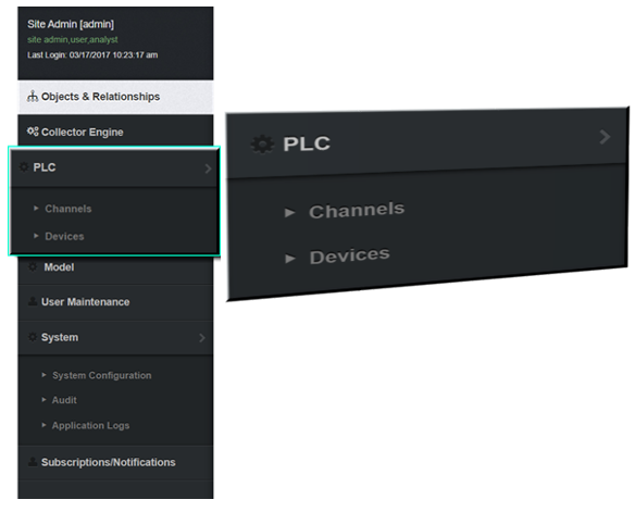
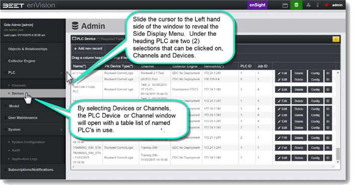
When you slide the cursor to the left-hand edge of the window, the Admin menu appears. Under the heading, PLC is two (2) selections that can be clicked on, Channels and Devices.
PLC Function
The Channel information is used by the EDC server to setup how data is transferred between the different PLC devices and the EDC. Each channel is like a separate connection as far as the EDC is concerned. This means it can be communicating simultaneously with each PLC. This can be considered the recommended default setting. The trade-off with having independent channels for each processor is that it adds more traffic to the network at any given point in time. When there are many PLC processors connected to an EDC it may become necessary to have PLCs share channels to reduce the amount of traffic on the network. When PLCs share a channel, the EDC will read data from them in a sequential fashion rather than simultaneously. The Channel selection is used to set up the sharing of channels between PLCs. The trade-off with PLCs sharing a channel is it takes longer for the EDC to read data from the PLCs since it is reading data from one PLC, then the next PLC, and so on, until it reads the last PLC on the channel and then repeats the sequence. The potential is that data may change in the PLC before the EDC was able to read it. There are options available to help reduce the risk of missing data. The Channels selection is usually only important when an EDC is going to be talking with many PLCs, say more than 4 or 5. The amount of data being read from a particular PLC could also play a role. These situations need to be addressed on a case-by-case basis.
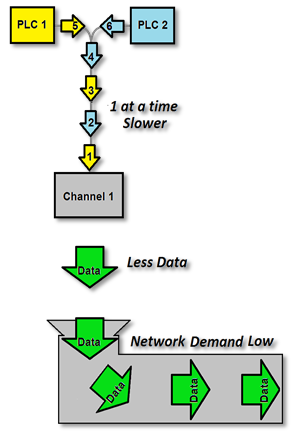
One Channel setup with Multiple PLCs (2 or More)
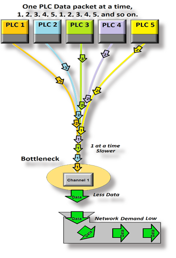 If a cycle time would take several seconds to minutes, one channel can be used for multiple PLCs. Each PLC will send off a data package into the channel. The Channel will read each PLC one at a time in order. When the last PLC is read, it goes back to the 1st PLC.Because the typical channel can only perform one action at a time. If there were 2 or more PLCs, then it would create a bottleneck at the channel input. It would only be able to process one action at a time. 1 action from PLC 1, then 1 (2) action from PLC 2, and so on. This setup is typically s l o w e r through the channel, but also creates less demand or traffic, on the network. If the cycle time is high and data requirements are low, then this would be a good setup to use. This system configuration is slower but has less demand on the network if used.
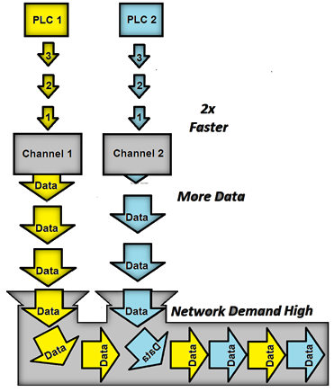
Two Channels Setup with 1 PLC Each
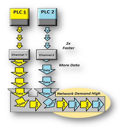 In the event of a very low cycle time, where the cycle time would be millisecond to a few seconds, it would be better to use multiple channels with a single PLC. With 2 channels with a PLC for each, it would be able to process the data faster. The bottleneck would be eliminated. However, using this setup would create greater demand or traffic, on the network.This would also be the case if you have different models of PLCs. Two different PLCs cannot run on the same channel. Therefore, it would be necessary to have a separate channel for each PLC. You have to take caution that too much demand on a Network connection can cause a series of issues such as flooding the network, saturation, and cause backlogging resulting in packet losses as well as other problems.
PLC Devices
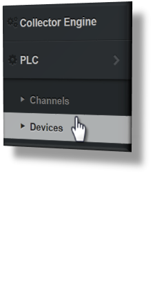
Click on Devices under PLC heading inside the menu.
The following window appears. The data currently shown in the screenshot is data that was created in a test environment. It gives an idea of what a system with many PLC devices would look like. In the Admin menu, click the + Add new record button.
Click the + Add new record button and a series of options will appear, text boxes to name the Device and Network ID. Dropdown menus for Plc Device Type, Channel, and Collector Engine. And a selector for PLC ID and Job ID as well. Enter the information for the PLC device you are adding, then click the update button.
The Name![]() field is where you enter a name for the PLC. For this example, Test is the processor name.
field is where you enter a name for the PLC. For this example, Test is the processor name.
The Plc Device Type![]() field utilizes a pulldown menu from which you select the type of PLC that you are connecting. For this example, Rockwell ControlLogix was selected from the menu.
field utilizes a pulldown menu from which you select the type of PLC that you are connecting. For this example, Rockwell ControlLogix was selected from the menu.
The Channel field can be left blank. A Channel with the same name as the Collector Engine will automatically be created and inserted into the field when the Update button is selected.
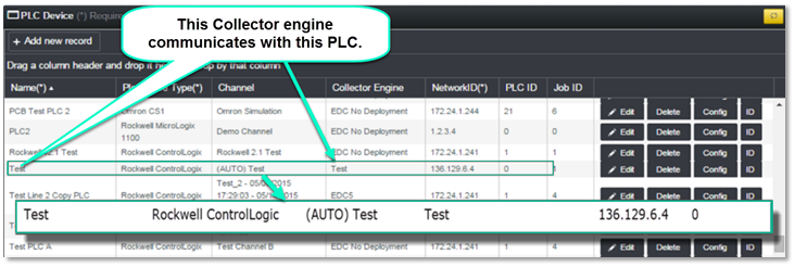
The Collector Engine field is where you enter the Collector Engine name that was created previously. The Test, is the Collector Engine name that was created for this example. The Collector Engine named "Test" communicates with the named PLC Device "Test".
The Network ID ![]() field is where the Ethernet I.P. address for the PLC device is entered. For Rockwell, this typically would be the I.P. address of one of the Ethernet modules in the chassis where the PLC resides. This would be based on how the EDC is networked into the PLC network. For this example, 136.129.6.4 was used.
field is where the Ethernet I.P. address for the PLC device is entered. For Rockwell, this typically would be the I.P. address of one of the Ethernet modules in the chassis where the PLC resides. This would be based on how the EDC is networked into the PLC network. For this example, 136.129.6.4 was used.
The PLC ID is an Integer reference number for the PLC device.
The Job ID is the number of the job agent that will process the collected data. For advanced users only, a performance increase may be possible by distributing the processing load among multiple job agents.
Once all of the parameters are set and you approve, click the Update, to save.
PLC Channel
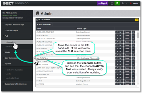
The PLC Device, named Test, is created and added to the list of available PLC Devices. Note that the Channel field has an entry of (AUTO) Test shown. This indicates that a Channel named Test was automatically created when you created the PLC Device since the Channel field was left blank.
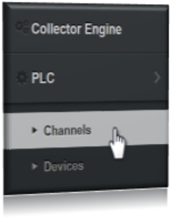
Click on the Channels button on the LH side menu and see that the channel (AUTO) Test was created.
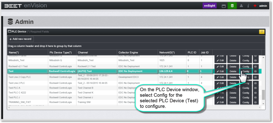
The next step is to configure the PLC Device. Go back to the Admin Display Menu, and select Devices under the PLC Tab. The configuration selections are based on the PLC type (Rockwell, Siemens, etc.). For this example, we will be dealing with configuring a Rockwell ControlLogix PLC Device. Click on the Config button for the PLC Device named (Test) that you would like to configure.
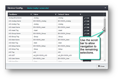
The following window pops up. Not all the selections can be seen at one time in the window. There is a scroll bar to allow navigation to the remaining selections. Multiple screenshots will be utilized to show all the different available selections. There are only 6 or so selections that should ever be modified and so those will be focused on. The remainder should use the Default Value unless there is a sound reason to change them.
In the Device Config. 1st screenshot all the Parameters shown should be left with their Default Value. They are shown in the Device Config. list for informational purposes.
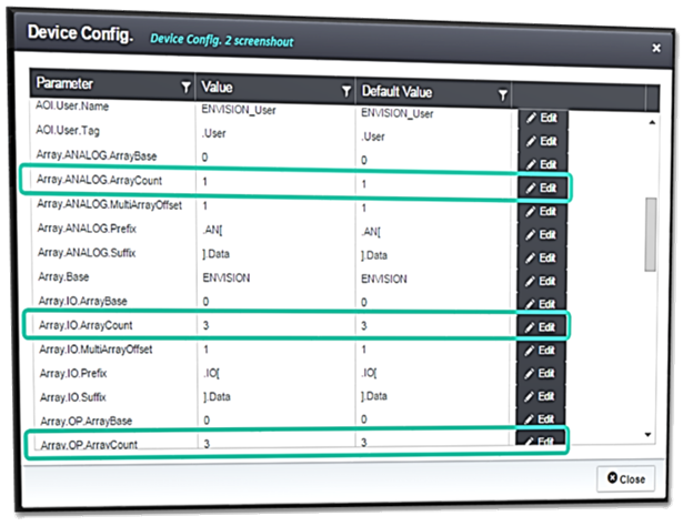
In the Device Config. 2nd the screenshot 3 Parameters can be modified based on the specific application that is being monitored. If the Envision application is designed to store analog data or if the PLC has fast-changing data then either of these can impact what values are entered for these specific parameters.
Array.ANALOG.ArrayCount
Array.USER.ArrayCount |
1 |
1 |
!Edit. |
This value (Array.ANALOG.ArrayCount) can range from 1 to 5. If the specific Envision application is not designed to capture any analog data then this Value should be left at its Default Value of 1. If the Envision application is designed to capture analog data then it is recommended that the Value be changed to 5. The PLC driver will use 5 identical arrays that will store Change Of State (COS) data for all analog signals in a cyclical manner. 1st COS will be stored in array 1, 2nd COS in array 2, 3rd COS in array 3, 4th COS in array 4, 5th COS in array 5, 6th COS in array 1, 7th COS in array 2, etc. This allows the EDC to capture fast-changing data even if the OPC (Kepware) is not as fast as the PLC scan time. The OPC will read all 5 arrays every time it accesses the PLC database.
Array.IO.ArrayCount
Array.IO.ArrayCount |
3 |
3 |
!Edit. |
This value (Array.IO.ArrayCount) can range from 1 to 5. The Default Value of 3 is recommended to be left unchanged. Data in the IO array can sometimes have COS in consecutive scans of the PLC. This usually occurs near the end of a cycle and the beginning of the next one. Since the COS of data in the IO array is "fast" only at certain points and only for 2 or 3 PLC scans having the number of arrays used set to 3 is usually sufficient. The PLC driver will use 3 identical arrays that will store Change Of State (COS) data cyclically. 1st COS will be stored in array 1, 2nd COS in array 2, 3rd COS in array 3, 4th COS in array 1, 5th COS in array 2, etc. This allows the EDC to capture data that may have changed in back to back scans of the PLC even if the OPC (Kepware) is not as fast as the PLC scan time. The OPC will read all 3 arrays every time it accesses the PLC database.
Array.OP.ArrayCount
Array.OP.ArrayCount |
3 |
3 |
!Edit. |
Array.OP.ArrayCount – This Value can range from 1 to 5. The Default Value of 3 is recommended to be left unchanged. The same explanation used above for Array.IO.ArrayCount holds true for Array.OP.ArrayCount.
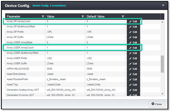
In the Device Config. 3 screenshots there is 1 Parameter that can be modified based on the specific application that is being monitored. If the Envision application is designed to store User data and the data is fast-changing then that will impact what value is entered for this specific parameter.
Array.USER.ArrayCount
Array.USER.ArrayCount | 1 | 1 | Edit.
Array.USER.ArrayCount – This Value can range from 1 to 5. If the specific Envision application is not designed to capture any User data, then this value should be left at its Default Value of 1. If the Envision application is designed to capture User data, then this value can be modified if the data is fast changing using the same explanation given for Array.ANALOG.ArrayCount. (Note: USER Array is currently unavailable. Future releases of Envision will incorporate this feature).
In Device Config.4 screenshots 3 Parameters can be modified based on the specific configuration of the PLC hardware and how the connection is made between the EDC and the PLC.

PATH | 1 | 1 | !Edit.
This Value helps describe how the EDC (specifically the Kepware OPC) will connect to the PLC database after it has established communications to the Network ID entered for the PLC Device (136.129.6.4 for this example). For Rockwell, a Value of 1 indicates that the PLC processor is accessed via the chassis backplane where the processor is installed. This is the most common method of connecting to a Rockwell PLC. This means the EDC is connected directly to an Ethernet communication module that is mounted in the same chassis as the PLC. There are other scenarios where the network between the EDC and the PLC is more complex and subsequently causes the PATH parameter to be more complex. You will need to refer to the Kepware manual that specifically addresses the different communication network setups that it supports for Rockwell processors to determine what the PATH value should be for these situations.
https://www.kepware.com/products/kepserverex/drivers/allen-bradley-controllogix/documents/allen-bradley-controllogix-ethernet-manual.pdf
Program.Name | ENVISION | ENVISION | !Edit. .
This parameter (Program.Name) defines the program name that the Envision PLC software driver will be called when it is imported into the ControlLogix project file. The Import file (*.L5X) is created when a Deploy is performed. It is recommended that the Default Value of ENVISION is used unless it is absolutely necessary to change it. One situation where the Program.Name parameter would need to change is if there is more than one (1) Envision PLC driver program imported into a PLC. The Envision PLC program names will need to be unique in this scenario. One Program.Name could be ENVISION and the other ENVISION_A for example. The Program.Name is used by EDC to find the program scoped tags that it needs to access.
SLOT | 0 | 0 | !Edit.. .
This parameter (SLOT) is used to define the slot within the PLC chassis that the PLC processor is installed. This value is used by the EDC in helping define the communication path between the EDC and PLC. Typically PLC processors are mounted in slot 0 although they can be mounted in any slot. Modify this parameter as needed.
Editing Asset Tags
Asset Tags are used to convey additional information to the Envision application for display purposes and also for reporting calculations. To access the tags in Admin mode, highlight an object at the Asset level in the Factory tree window and then click on the Tags button.
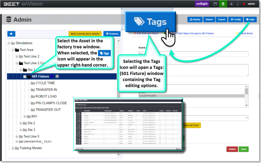
The following window appears: Here is a zoom-in of the most frequent tags used for cycle recording.
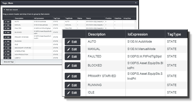
PLC Tags
PLC tags have already been assigned in this example for the I/O Expressions. The Asset Tags themselves are self-explanatory. AUTO, MANUAL, FAULTED, BLOCKED, PRIMARY STARVED (and also SECONDARY STARVED which isn't used in this example) are used to draw lines when looking at cycle history with Sequence View enabled to indicate when any of these signals changes state.
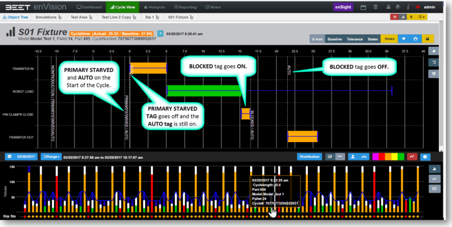
Below is an example of how Asset Tags are displayed in the Cycle view screen. Note: Must be selected for sequence view.
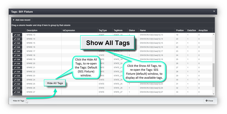
There are other Asset Tags that can be edited. To see these, click the Show All Tags button located at the lower LH corner of the window.
PLC Setup and Configuration
In the event, that a cycle time would take several seconds to minutes, one channel can be used for multiple PLCs. However, the typical channel can only perform one action at a time. If there were 2 or more PLCs, then it would create a bottleneck at the channel input. It would only be able to process one action at a time. 1 action from PLC 1, then 1 (2) action from PLC 2, and so on. This setup is typically slower but has less demand on the network. If the cycle time is high and data requirements are low, then this would be a good setup to use. This system configuration is slower but has less demand on the network if used.
Two Channels Setup with 1 PLC
In the event of a very low cycle time, where the cycle time would be millisecond to multiple seconds, it would be better to use multiple channels with a single PLC. With 2 channels with one PLC a piece, it would be able to process the data faster. The bottleneck would be eliminated. However, by using this setup, the demand on the network would be greater.
This would also be the case if you have different models of PLCs. Two different PLCs cannot run on the same channel. Therefore, it would be necessary to have a separate channel for each different PLC. You have to take caution that too much demand on a Network connection can cause a series of issues such as flooding the network, saturation, and cause backlogging resulting in packet losses and other problems.