Models
In ENVISION Models have significant importance. Models are used to signify a major motion path that needs independent baselines assigned to these motions. It must have a valid IoExpression entered for Asset cycles to be captured. The Envision application uses the MODEL tag as a pointer to the appropriate baseline cycle time values entered for each group of the Asset. Options are used to signify part type differences where the major motion remains the same and existing baselines and tolerances can be used. Options are generally used for reporting purposes.
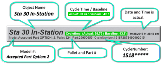
At the top of the Cycle View window, you will see the following tags now visible: CYCLENUMBER, PARTNUMBER, MODEL, OPTION, and PALLET. These tags are 32-bit values. The MODEL tag has significant importance. NOTE: It must have a valid IO Expression entered, for Asset cycles to be captured. The Envision application uses the MODEL tag as a pointer to the appropriate baseline cycle time values entered for each group of the Asset. You define the models and their values in a different area of the Admin environment. This is shown in detail elsewhere but a short example of what the MODEL tag is used for and its significance is shown below.
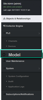
Slide the cursor to the left side of the screen to open the Admin Display menu. From the side menu, select the Model (Tab) from the side Admin Display Menu.
A list of the PLC devices that have been defined appears. You select the PLC that was entered for the PLC Device for the Asset. For this example, the PLC Device is TRAINING_SIM_STA. Click on it.
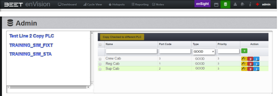
The following window appears. In this example, 3 models have been created. The Part Code values are the numbers that the Envision application expects to see returned by the tag name entered in the MODEL Asset Tag. S130VRoll_SR.Model is the tag name that was entered for this example.
Adding, Editing, and Deleting
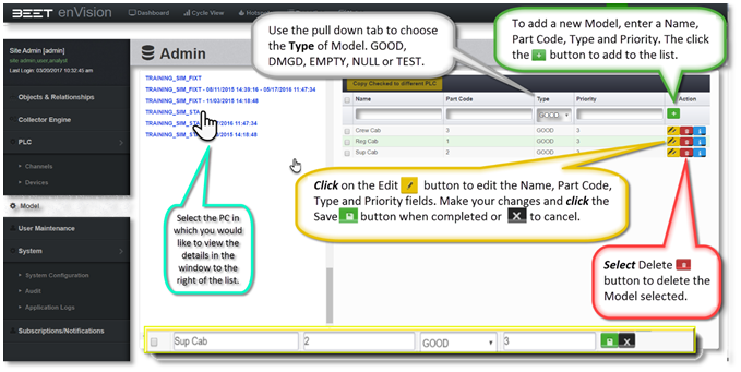
From this Model screen, several types will be listed in a table. These are the types that were previously inputted earlier from when the test was set up. They can be.!. edited or.3. deleted. You may also add to the list by simply filling out the fields above the list. Enter the name that you would like to call it, the Part Code, Type, and Priority. Then click the. +. button to add it to the list.
Name
Enter a name that is unique to the object you are using. For example, above, there are 3 different Cab configurations, Crew, Regular, and Super Cab. To add the Extended Cab (Ext), we would enter Ext under the name dialog box.
Part Code
A part code can be an actual part number or merely a designation number to show a difference between parts or similar parts. In the example above, the different types have a simple number to designate their Part Codes.
Type
In this part of the Table, there is a pull-down tab to which will give you a selection of choices to choose from. They are GOOD, DMGD (Damaged), EMPTY, NULL, and TEST. These labels or strings are configurable to make it whatever you deem as needed. They are common types in manufacturing. The label can be tagged so the PLC can know what is in the system at that time.
In the case of manufacturing, the choice of GOOD would be picked in the production of parts. DMGD selection would represent a part or process that could not be completed due to an incomplete process or stoppage.
- GOOD
- DMGD
- EMPTY
- NULL
- TEST
Priority
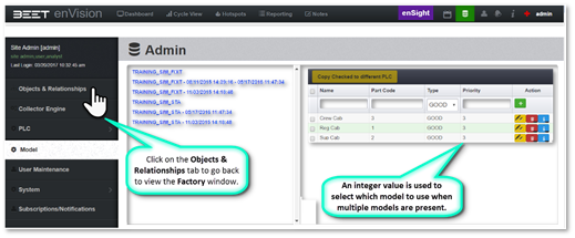
An integer value is used to select which model to use when multiple models code are collected during a cycle. It is since a lower number is a higher priority. As in the number 1 priority would be higher than 2 or 3.
Once the Model data has been created, baseline values can be entered for the Groups that comprise the Asset. This is shown in the following screenshots. Drag the cursor to the left-hand edge of the screen for the Admin menu to appear. Click on Objects & Relationships to go back to the Factory Window.
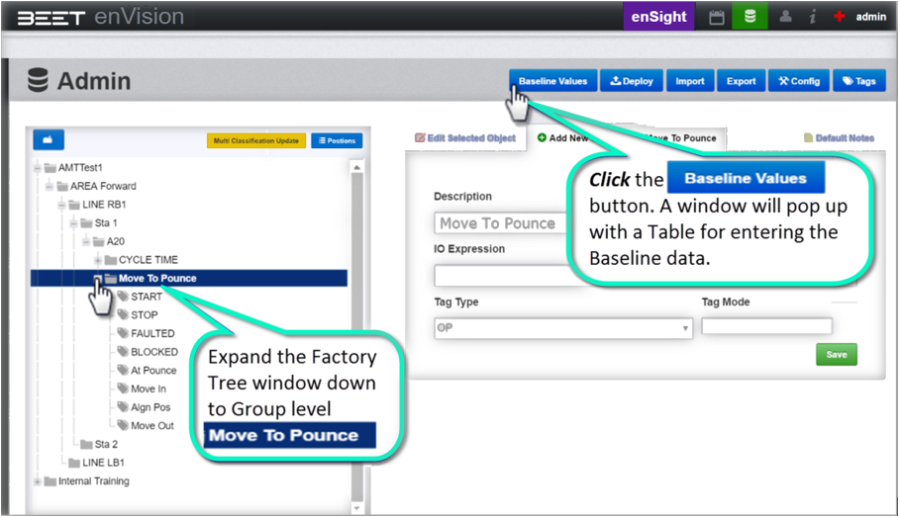
Expand the tree in the Factory window as shown. Then highlight the CYCLE TIME (GROUP level) and click on the Baseline Values button. A window will pop up with a table for entering Baseline data parameters.
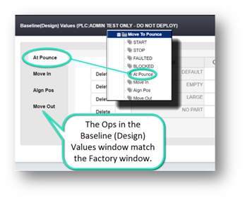
The Baseline (Design) Values window will reveal. From here, the values of the Group Ops are inputted. In this example, all the values are inputted in for At Pounce.
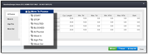
There are 3 other objects, Move In, Align Pos, and Move Out, that will need to have the values inputted as well. Click on the object tabs to input your values.